home
introduction
build
sva tests
links
latest updates
February 1
- Inventing the egg -
Went out to the garage determined to rivnut the side pods on. Did some measuring, and determined that whilst I'm sure they're OK longitudinally, I've no idea where to fix them laterally - until the rear tub is on. So, I just taped them on, and covered the cage in masking tape in preparation for lowering the bodywork over it. Maybe tomorrow...
February 5
- Juggling bodywork -
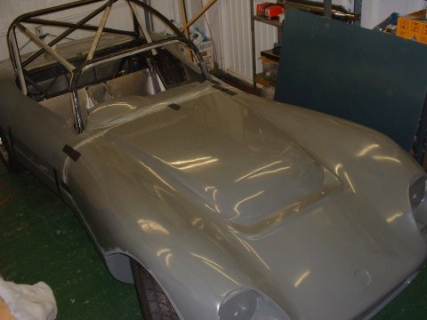
Having marked up holes in the bodywork last night, this morning came time to cut them. My plan was this - cut the front ones so that I could slide one front corner around the cage, then rotate the bodywork to locate the other side, and then slip the bodywork down over the back of the cage.
Sounds great, doesn't it; but it didn't work in practice. After a couple of hours, and ever increasing amounts of GFRP removal, I found that the best technique for getting the bodywork on is in fact this: Lower the bodywork flat over the cage. Make the front holes wide enough to be able to slip through the cage quite near the top, and deep enough to allow the bodywork to be rotated at the back far enough for the rear part to slip down over the cage. The holes at the back should be deep enough that once the back of the bodywork is resting, the back can be lifted up and forwards over the seat belt bosses, and the front will fall (crash) into place.
So, in the end: my holes at the back are perfect; the ones at the front are much much too big - I've going to have to patch them up.
The next 3 hours were spent juggling the rear bodywork, the sidepods and the bonnet, to see where the best place for all was (with a bit of assistance from DH2. One thing I learned was that I needn't have worried about mounting the sidepods - the rear body work doesn't need them for support. I ended up just taping the pods to the rear bodywork to find the correct height for them, and this turned out to be 3/4" higher than I'd originally thought, so I'm glad I didn't fix them in place earlier in the week.
I also ended up moving them 15mm forward - if I pushed the bonnet all the way up to the rear tub, the front wheel arches didn't clear the wheels, so I had to pull it 15mm forward, hence the rear tub, hence the pods. This means unfortunately that the wheels bump into the front of th sidepods on somewhat less than full lock, so I'm going to have to undertake some butchery of the sidepods - my fault for choosing super high profile tyres...
February 6
- Lazy day -
Lazy - and boring too. Spent a couple of hours tidying up and drilling the sidepod rails.
February 7
- Pad rails finished -
Popped out to the garage when I got back from work and riveted and bonded the side pod rails on. Also started to drill them out for the M5 rivnuts I'm going to be using to hold the sidepods on. Got forced inside by hunger 
February 9
- Sheesh - more juggling -
Tonights task was to bolt the sidepods on and check alignment with the rear tub. Nothing lined up, of course - every step forward you make, it changes something, and you have to re-align everything. Still -in the end, it wasn't too bad - I had to move one pod out by 7mm at the middle.
Tomorrow's job appears to be fixing the bottom of the pod in place so that the top surface of the pod is parallel with the bottom surface of the tub.
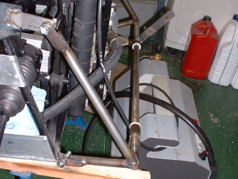
- No room for exhaust -
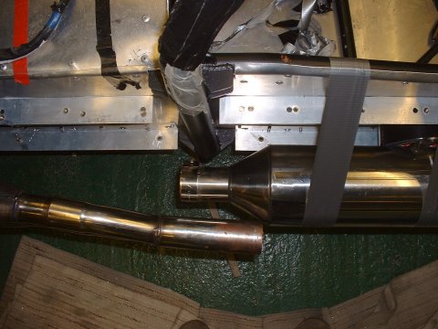
I discovered yesterday that the exhaust won't fit inside the side pod - the back corner of the silencer is 10" from the side of the car, but the pod is only 9" wide... I rang Ian to ask him if I was missing a trick and he didn't seem to think so. "Hmmm. Mine doesn't do that. You'll have to cut and shut it. I don't use that exhaust guy anymore..."
Sigh. I'll have to cut a wedge out of one section and get it re-welded. ChrisG on Cam7 has volunteered, but he lives many miles away. I'll ask Tim as well, as he's just round the corner. The picture shows both where the can should be, and where the pipe into actually is...
February 12
- faffety faff -
Now that the sidepods are in the right place, I drilled the rest of the mounting holes and fixed the rivnuts in place.
- Mudguards -
I figure the SVA man won't be that happy if the cockpit is open to the rear wheels, so I've made some mudguards
Now, I have to figure out how to attach them permanently to both the side of the car, and the sidepod, which is, if you'll remember, detachable.
February 13
- Template -
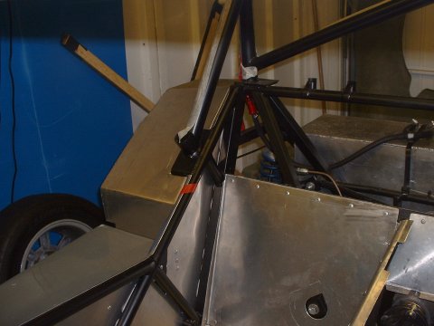
Time to make a dashboard! Here's a picture of the template I've made up.
One of the tricky things about the dashboard is that for SVA, the lower edge has to rounded to a radius of 'not less than 19mm'. DH2's Westfield, and I guess therefore all the others are in flagrant violation of this little detail, but we'll let that lie. In my case, the roll cage has a horizontal 1.5" member that runs from one side of the car to the other, about 2" forward of the dashboard panel, so I've out a bend in the bottom of the panel to meet that.
- Cut... -
I cut a wedge out of the exhaust pipe - taking lots of care to mark it all up nicely, trying to get a symettrical flat cut. I nearly managed as well. Now I just need to corner Tim to do the welding. He's making some sort of excuse about having lots of work to do. PUT YOUR PETTY CONCERNS TO ONE SIDE - I'VE GOT A CAR TO BUILD, MAN. Sheesh.
February 15
- Steering column needs a hole -
Sterling effort today - 20 minutes in the garage, in which time I cut a hole in the scuttle for the steering column to poke through. Forgot to put on a dust mask, and have breathed in more glass fibres than I'd care to think about. Also realised that firing up the jigsaw at 22h00 may not have endeared me to the neighbours.
- -
On the upside I have fixed a bug in the code that I wrote to generate this website which meant that thumbnail links were getting badly processed.
February 19
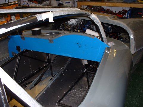
- Attaching the bonnet -
The early part of today was spent making brackets for bonnet hinge to attach to. There's no obvious place to attach it, but it looks lihe there should be - must be a hinge for a standard Phoenix. It took quite a long time, because there's lots of: taping the bonnet in place; offering up the hinge; removing the bonnet and putting it out of the way (not that easy in a small garage!); offering up the hinge; repeat as necessary steps.
After quite a few repeats and a bit of welding, the hinge ended up almost exactly where I wanted it (it has to be low and forwards enough to allow the bonnet to tilt forwards without hitting the ground, but high and rearwards enough to not get in the way whilst the bonnet tilts).
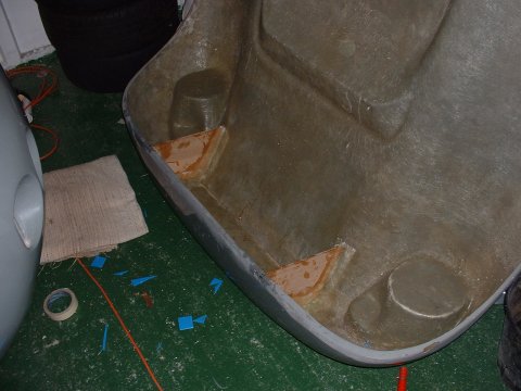
Next! - the hinge has to have something to attach to. The recommended approach is bond in some 1/4" plywood, so that's what I did. My first ever bit of GFRPing - looks better in the pictures than in real life...
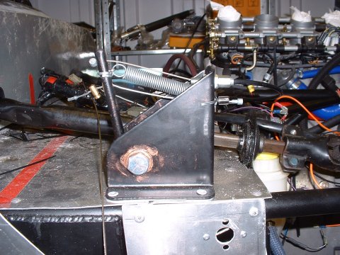
- Finishing touches -
I added the throttle's return spring whilst looking for something better to spend my time on.
February 20
- Attaching the bonnet -
This morning, the GRFP seemed to have all set OK (good job too since I'd left the heater running all night to keep the temperature up). I cut a couple of clearance slots in the bonnet flange, and mounted it on the hinge. Very satisfying - I'd been worried about this job since almost Day 1, and it seems to have gone OK.
February 27
- Tidying up -
My notes on what I did today are a little vague - "5 hours on loom". Goodness knows what I was doing. Still, another note reminds me that I did find the elusive anti-theft bypass resistor, and it is, as suggested in many other places, 100ohms.
This seems as good a time as any to mention that the 'mysterious resistor pack' mentioned elsewhere is no longer so mysterious. Suzuki have confirmed the date of manufacture of the engine as 2001, not 2002 as Ian had been told. Looking at the wiring diagram reveals that the 2001 bike has a fuel level sender resistor pack. I imagine that it can just be left out completely if the built in fuel level sender is not being used. It also answers the small (previously unasserted) mystery about why the fuel pump has 4 wires instead of 3.
Ah - now I remember. I was starting work on the feeds to the fuse box and relays. I acquired from SteveW, quite some time ago, a couple of 70A relays. I pressed one of these into service to act as the switched feed for the chassis loom, as there is no chance of any part of the bike loom coping with the demands that I will be throwing at it (including driving lights, spotlights, foglights, heated driving suit etc
The actual switched feed from the bike loom I used to feed the headlight switch. The unswitched feed I make no explicit use of, although it does provide power to the ECU, clocks and the no longer mysterious resistor pack.
By the end of the day, I'd basically got the ignition circuit working, having taken off the original bike switchgear, and run wires to my own.
February 28
- Making the dash -
At the end of yesterday, I realised that there are only so many wires you can run around to the dash area without there being an actual dash to attach them too. It gets real complicated. So I made the aluminium version of the dash from the template I'd made up before.
I drilled all the holes using a step drill. It's quite a handy thing, but seemed to have a habit of wandering off centre a bit, as not all my holes ended exactly in line with each other. But the ease of drilling large holes of different sizes without having to change the bit was a big plus.
This page last updated on: Thursday, Aug 24 2006
Component
january 04
february 04
march 04
april 04
may 04
june 04
july 04
august 04
september 04
october 04
november 04
december 04
january 05
february 05
march 05
april 05
may 05
june 05
july 05
august 05
november 05
december 05
january 06
march 06
april 06
august 06