home
introduction
build
sva tests
links
latest updates
November 3
- Fitting the tank -
I'd taken the fuel tank to Mackays last week to get a plate welded on for me to screw the fuel sender into (the previous adaptor made for me by JB7 was sacrificed in a horrendous Lumiweld accident). Today I got it back, so I was able to flush all the little bits out of it, and fit the fuel pump and sender.
I also spent a bit of time Lumiwelding a large washer into the base of the tank filler cap, which reduces the hole to the SVA acceptable 23.6mm.
remaining jobs at this time, then, are to secure the tank in place with some humungous cable ties and to fit the filler cap - but I can't do the latter until I've got the bodywork on.

November 12
- Fitting the handbrake -
Today I approached a job I'd been putting off for a while, which was figuring out and implementing the gubbins need to attach the handbrake to the handbrake cables.
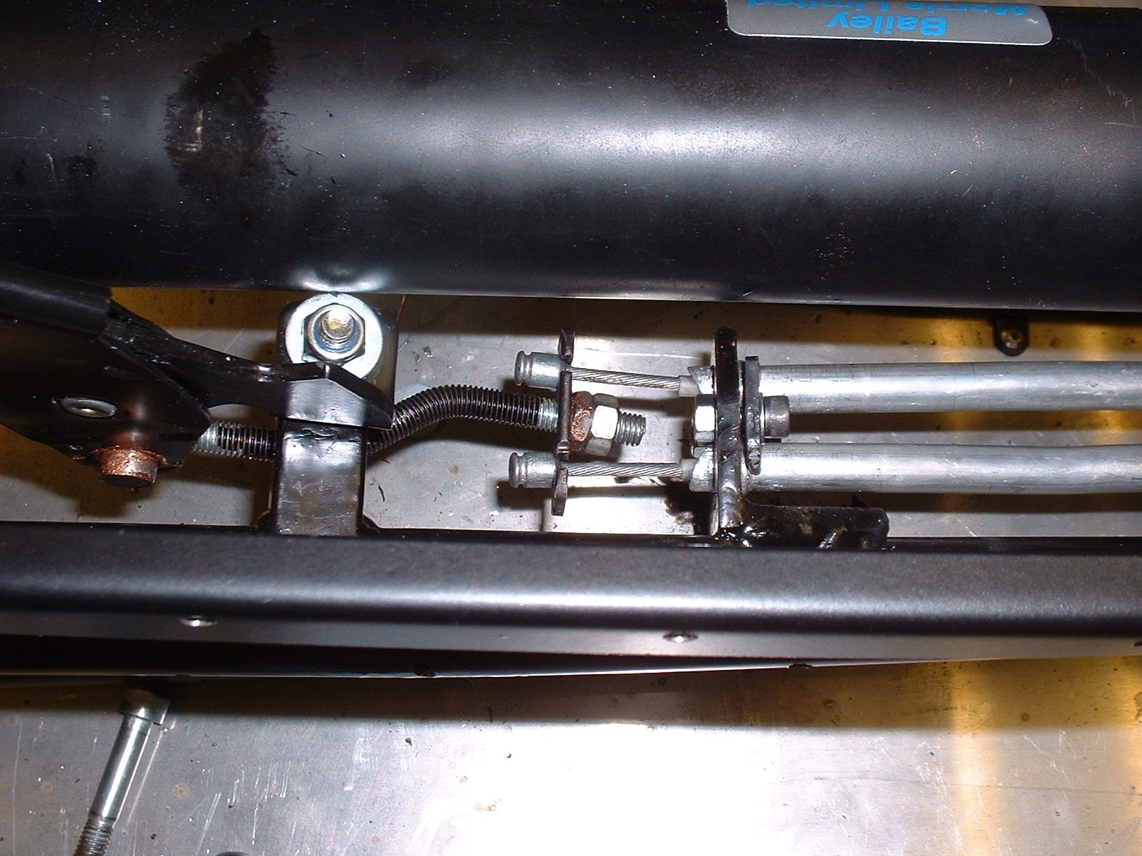
A picture says 1000 words so here's the result, and since I've had complaints that this website has too many words, here are some pictures instead:
 | |
 |
 |
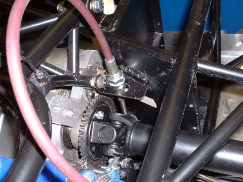
By my calculation that's 3000 words saved, but perhaps a little explanation is permitted? The copper-grease covered nut roughly dead centre of the upper picture has been rounded, and hardened, on the face butted against the cable puller plate, in order to allow it to swivel. In combination with the kink in the threaded puller rod (which is free to rotate), this allows the cables to balance themselves when the lever is pulled.
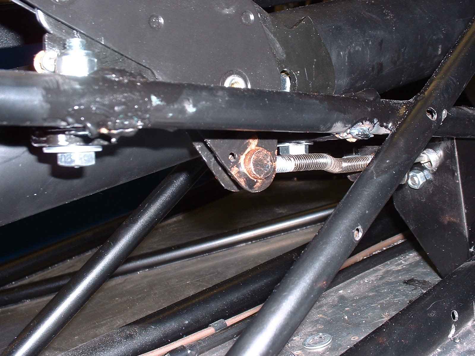
The second picture shows this arrangement from the back, and the cable clamp plate that stops the cables falling out of the cable stop plate that's welded to the chassis.
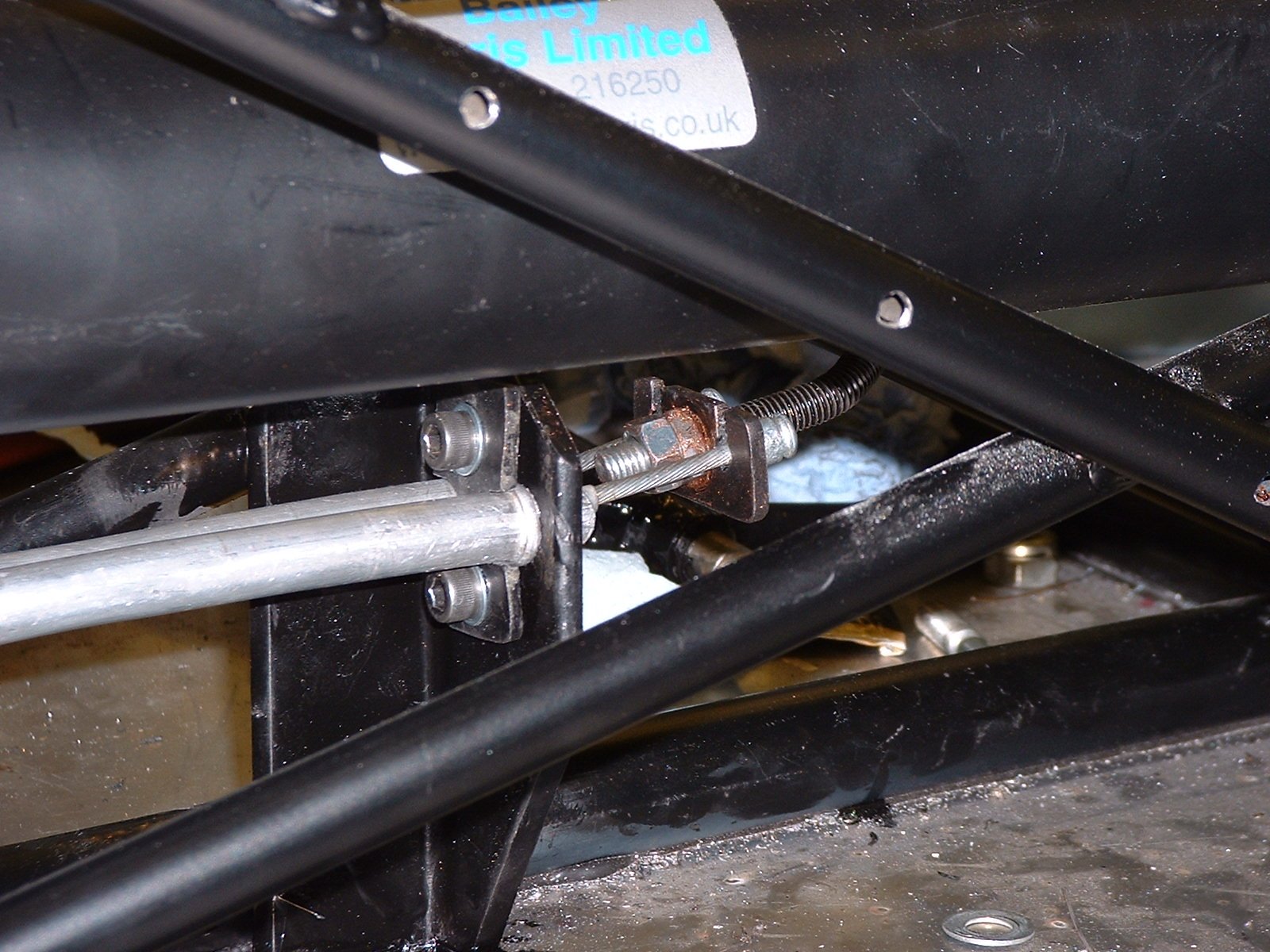
The third picture shows where the threaded cable puller threads into the 1/2" pivot I fitted into the handbrake lever. I had to seperate the 2 halves of the lever a bit to accomodate the puller rod, but nothing too extreme.
All in all, I'm pretty happy with how it's worked out (that's a line straight from Paul Jr of American Chopper isn't it?) - the only bit that I'm not sure about is the plate in which the cable barrels sit - I can't tell whether or not the cables can vibrate out through the slots in the plate. I think a better solution would be to find some circlips for the grooves in the barrels, and get the plate to pull on those instead. We'll see!
November 13
- Fitting the steering quick release boss -
Super good news today. I'd been worrying about fitting the quick boss for quite some time. Tim kindly allowed himself to be volunteered to weld it on, but I was faced with the task of setting up a jig to get the boss perfectly central. In a flash of inspiration this morning, I found that the M10 bolts I had were an almost perfect fit (a teeny weeny slightly bit too big, actually) through the centre of the boss - so I put the boss on, put a bolt through it into the top of the column and welded the boss to the bolt. Finally, an M5 bolt through the bottom of the boss to stop any possible rotation of the M10 bolt in the top of the column, and Bob's your uncle - a perfectly central, solidly mounted boss.
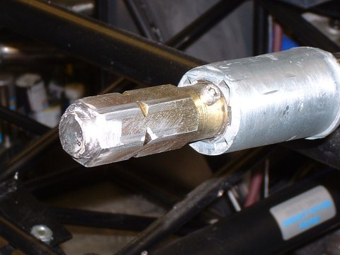
As you can see, I had to do a fair amount of angle grinding after the welding - the quick release mechanism butts right up to the top of the column, so any weld material had to be removed. If I had to do it again, I'd round off the corners of the bolt head (with some emery paper) and arrange for the top of the head of the bolt to end up 1 or 2 mm inside the boss, so that all the welding was inside the boss.
- Fitting the engineside gear stop -
The disadvantage of using a cable for the gear shift is that it needs stops at each end. I spent a little time in October figuring a way to achieve this at the engine end and the most obvious idea was to weld a plate perpendicularly onto the outside of the pedal box. Making up a alumium template, it became clear that at the height that the plate needed to be to give the cable the right amount of travel up and down to actuate the gears, the it would be possible to attach one edge of the plate to the engine cradle as well, to give extra stiffness. Downsides were that the cable has to run within a couple of mms of the prop, and that the arm of the lever on the gear shift shaft would need to be bent through 45° to meet up with the cable.
So today, I did all of those things. You can see from the first picture that in the month in between the initial concept and the implementation, I forgot about the propshaft, and had to move the cable hole in the plate to move the cable closer to the pedal box.
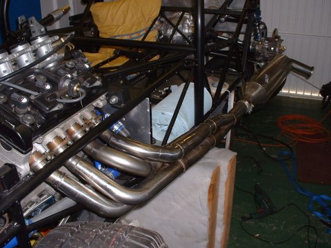
- Dry fitting the exhaust -
With the time rapidly approaching to fire up the engine for the first time, I thought I'd better check that the exhaust fitted. After diassembling it and bolting the headers on seperately, I found, much to my surprise that it does. It sits about 1ft from the chassis at the back end - I guess it become obvious what to attach it to once the side pods are on...
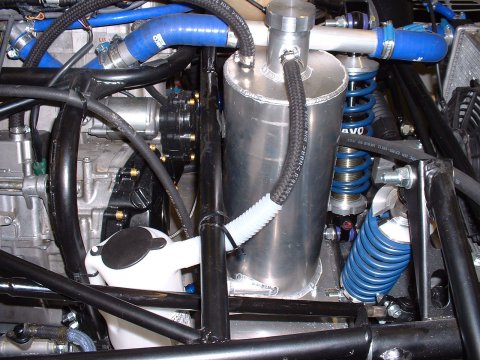
- Fitting the catch tank -
Hardly an exciting job, but in the spirit of keeping the word count up, I hereby report that I fitted the catch tank today. It's only an oil jug from the DT catalogue, but it was a lot cheaper than an aluminium one, and classier than a Coke bottle...
November 18
- Making Oil Cooler brackets -
Following the excellent suggestion of Mr DH2, I made up some brackets today that would allow me to mount the oil cooler to some spare mounting lugs on the Polo radiator. This took absolutely ages (no idea why, they're not exactly complicated), but I'm quite pleased with the result - they're shown here unpainted.
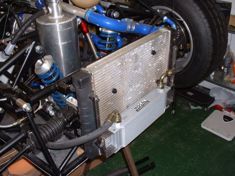
I also spent a huge amount of time attempting routing the oil cooler hoses, looking for some sort of route that wouldn't foul the dampers and/or the steering rack boots. Then I spent a huge amount of time tightening up the oil cooler fittings at the engine end. My advice, to you, Phoenix builder following in my footsteps, is to fit them before putting the engine in the car - much easier. And get yourelf a 22mm spanner.
November 19
- First fitting of the engine loom -
Oh what a joyous exercise this was. The loom that had been fitted to the engine, being from a race bike, had been stripped down to the minimum. Oh the upside, that means that someone's already gone through all the hassle of figuring out how to bypass the immobilisor, sidestand interlock, clutch lever switch, tip over sensor etc etc. On the downside, it meant that the loom, in critical area, bears little resemblence to that in the service manual.
It took several hours poking around with a DVM to finally figure out where everything was, and how it was all connected, except for the wires that used to go to the ignition switch, which seemed hopelessly interconnected. I fixed up all the things that I could see were wrong (the Clutch Position switch needed shorting out, as did the Tip Over switch and the EXCVA feed (for which credit must go to the instructions on Bugman's Gixxermods website)) and felt I'd got to the point where I'd checked as much as I could, and there was no choice but to plug it all in and see what happened.
Which was almost precisely squat. The secondary throttle servo rattled a bit, and and clocks showed a blinking indicator light. Which was wierd. After an hour or so of investigation, I came to realise that the main beam headlight switch had been wired up to be the ignition switch, but the engine kill switch and the starter switch were as Suzukisan had always intended.
Furthermore I realised that the handlebar switchgear Ian had given me from his box'o'bits was clearly not off the same bike, as it was fully expecting that the headlight switch should serve its original purpose of switching lights on and off.
And further to that, it was but a minor mental bound to realise as I'd bought the sub-loom for the clocks off someone with no apparent relationship to the race team, or Ian, it was almost certainly not going to be wired correctly. Or rather, it wasn't wired as incorrectly as required.
So I pulled some wires out here, pushed some in there and generally gave myself over to the mindset of the bloke that did the racer's loom conversion. Clever devil.
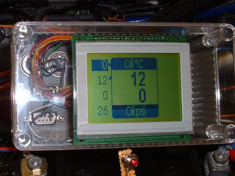
The next time I applied power - Bingo! The rev counter did it's thing, and the 'FI' error light came on. Shorting across the 'Dealer Mode' switch revealed the actual 'FI' error codes - and these indicated that the Inlet Air Pressure sensor, the Inlet Air Temperature sensor, and the Tip Over switch were all malfunctioning. The IAPS I haven't got (missing off the airbox), the IATS I'd forgotten to connect, but the TOS had me fooled for a bit; I'd shorted across where it should be in the loom. Leaving it open didn't change the error. In the end I realised that I needed some sort of resistor in the circuit to drop the voltage seen by the ECU to somewhere inbetween open and closed circuit - a 6.8k one did the trick.
The picture shows me doing 0mph, and the _C13 IAPS error code.
November 20
- A day of doom and joy -
Doom doom doom. I went to Hallens first thing to order an IAP sensor and a Starter relay (the latter not strictly necessary, but it would be easier to plug in the original relay than to wire in a new one). They quoted £40 for the relay and £250 for the IAP sensor. Despite some mental preparation for the shock of Suzuki parts prices, I wasn't ready for that...
The girl on the Parts Counter actually seemed as shocked as I was. She muttered something that may have been 'Sorry', but I was already leaving.
But then, some luck. A parts request on bike-breakers.info had me a IAP sensor and relay for the combined price of £35, which was much more tolerable...
My advice to you - make sure the airbox you buy has one on it. You may not be so lucky...
I spent the rest of the day fiddling with more loom stuff, but the end result was the same as when I'd started!
November 21
- Where does the time go? -
I look at the list of things I achieved today, and I wonder why it took so long. Fitting the oil filter, the coolant drain plug, the straps for the fuel tank. Perhaps I fell asleep?
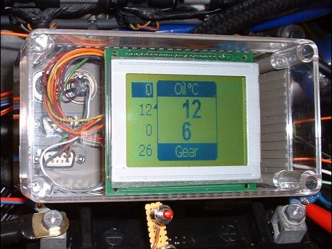
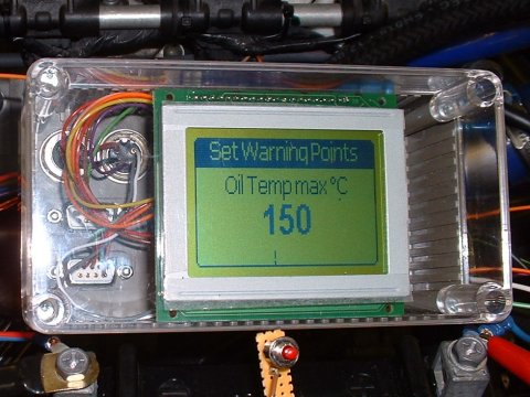
Mark came over in the afternoon and handed me the first prototype of the dash system he's been developing. My needs are simple - it shows Oil Pressure, Oil Temperature, Water Temperature, Gear and Fuel level, all of which are displayed at the same time down the edges, and 2 of them are shown larger, labelled, in the middle. It has an output to trigger some sort of warning device if any of the inputs go outside a configurable range, and another to switch the fan on (but not off, I've just realised). It has 3 buttons - in display mode the black ones cycle through the input to be displayed in the centre of the display, and the red one toggles to set mode, in which the threshold parameters for the triggered output are set.
I wired it up to the sensors and everything seemed to work, but it's hard to tell when you've not really got any useful input data  It seemed to think I was in 6th gear, even though the gear input line wasn't connected - I'll get Mark to investigate later. It should be easy to fix as the firmware can be easily changed from a PC For now I only care if it shows me oil pressure and water temperature when I get the engine running!
November 26
- Fiddle faddling about -
I spent most of today sorting out some of the easier electrical stuff. First job was to find a home for the battery - the lower the better to keep the CofG as low as possible. The best place turned out to be in the area in front of the brake and clutch master cylinders:
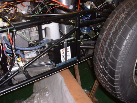
So that was the easy part. It took 2 hours the make the battery tray and the restraining strap...
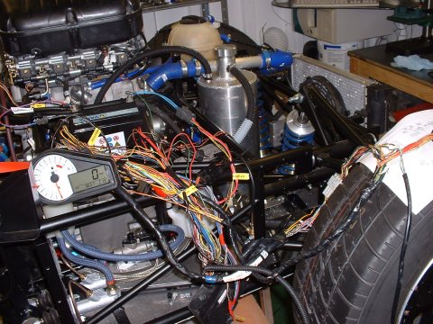
Then I rigged up a dummy under-scuttle panel to spread the loom out on, and worked out roughly where I want everything to go - which is to keep everything away from the exhaust side of the car, and to try and get the regulator into a place where I can get some airflow over it (other BEC's have had occasional problems with their regulators over-heating)
That done, I wired up the CKPS and the starter motor, as they'll be difficult to access once the coolant pipes are all in place and filled with coolant.
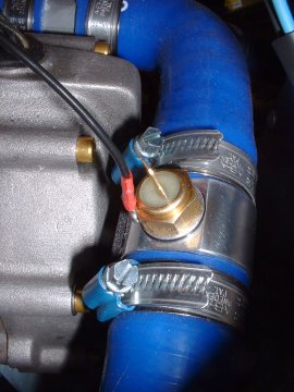
Then I went round checking that the various senders were properly earthed. The only difficult one was the coolant temperature sensor, which is in an aluminium hose joiner, which joins silicone hoses. I made up an aluminium washer with a tab on it for a spade connector, but it leaked when I trying putting coolant in the system. That left me little choice but to try and attach an earth wire to the sender itself. Soldering failed, so I tapped an M3 bolt into the side of it, which is perfectly not illustrated by the picture I took to commerate the achievement
The final dabble in electrics was to make sure that the coolant pump pumps. I can verify that it makes a whirring sound, and the coolant glugged a bit.
November 27
- Getting the engine going -
The only thing today standing between me and a running engine, all other things being well, is: to connect the fuel pump properly, to wire up a temporary connection to the radiator fan, and to get some petrol.
The first 2 were easily achieved, and for the latter I cycled off to the local petrol station with a small fuel can that DH2 had lent me. There's something decidely strange about cycling onto the forecourt of a petrol station, and stranger still is filling up a small container with petrol and putting it in your rucksack. I cycled home very carefully - I felt like I had a bomb in my rucksack.
So, petrol in, I turned the ignition on, and gratifyingly the fuel hose bucked a bit as it filled with petrol. I checked all round for fuel leaks, double checked that everything else was as it should be, set the coolant pump going and cranked the engine over. After a couple of huffs and puffs and wheezes she fired! Everything went as it should - good oil pressure, slow and steady climb in temperature that the fan controlled perfectly. There were no fuel leaks, coolant leaks, oil leaks or air locks and all 4 exhaust headers were hot.
Yay!
November 28
- Making the under-scuttle panel -
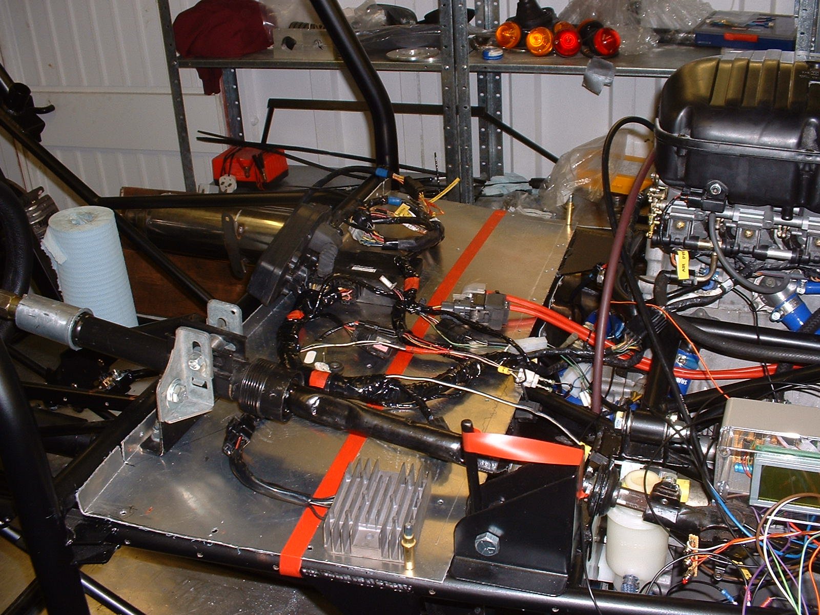
In order to have somewhere to put the various electric bits before I can have a little test run on the road, I spent today making the panel that supports the scuttle. The picture doesn't show it, but it's a really axkward shape in that it's not flat. A couple of saw cuts in strategic places helped it to sit a bit better.
The red line in the picture is roughly where the scuttle will rest. I want to put most of the unservicable bits behind this, and have the fuses, relays and other useful bits in front of it.
- Tidying the engine loom -
The latter part of today was spent bundling and wrapping the exposed wires in the engine loom - apart from anything else this makes it much easier to handle.
November 29
- Getting started on the driver end of the gear shift -
I spent an hour today making up some little plates to put in the tunnel to mount the gear shift lever too. Why does it take so long just cut 2 bits of metal and shape them a bit?
November 30
- Getting started on the driver end of the gear shift -
With Alex's help to hold the them in the right orientation, I got the plates welded in. Then I made up the gear lever itself, which is an upside down offset T shape. Through the unexpected arrival of some serendipity, I'd chosen some 1/2" x 16 gauge steel tubing for this; in metric, this gives a bore of 9.5mm, which is good enough for my purposes to be tapped for an M10 bolt. So it was easier than I was expecting to bolt the T in place between the plates. I'd put some nylon washers between the plates and the tube to reduce the friction, and in my original plan was that this would be all I would need to do. But as I twiddled the lever, there was too much friction, and backing the bolts off introdcued too much slack.
This page last updated on: Thursday, Aug 24 2006
Component
january 04
february 04
march 04
april 04
may 04
june 04
july 04
august 04
september 04
october 04
november 04
december 04
january 05
february 05
march 05
april 05
may 05
june 05
july 05
august 05
november 05
december 05
january 06
march 06
april 06
august 06