home
introduction
build
sva tests
links
latest updates
Electrics - what goes where?
- June 5 -
With the help of Tim's wiring diagram for his Fury, a Vehicle Wiring Products catalogue, and some coffee, I had a good bash today at working out what parts I need to order for the dash, dash loom and chassis loom . I have just a few simple goals. The bodywork is going to be removable, so I need to position connectors in sensible places; dash switches should be at least splash proof; and the dash needs to be SVA friendly. I'd really like waterproof toggle switches, but I think that even with their rubber booties on, their radius of curvature isn't big enough . I'll go and measure Tim's sometime. On the other hand, the SVA regs say that the minimum radius is only a requirement for protrusions that are rigid - a rubber bootie is defintiely squishy.
In a vague concession to sensibleness, I'm going to stick as closely as possible to standard colours for the looms, so I've contacted Chris, who has a heeuuge stash of thinwall cable in a variety of sizes and colours.
- June 18 -
I popped over to Hallens, the local Suzuki bikeshop, in the morning, and picked up some parts I had on order there - a rectifier, speedo sensor and the mysterious 'resistor' pack that connects to the connector that's not shown on any wiring diagrams for the bike.
First fitting of the engine loom
- November 19 -
Oh what a joyous exercise this was. The loom that had been fitted to the engine, being from a race bike, had been stripped down to the minimum. Oh the upside, that means that someone's already gone through all the hassle of figuring out how to bypass the immobilisor, sidestand interlock, clutch lever switch, tip over sensor etc etc. On the downside, it meant that the loom, in critical area, bears little resemblence to that in the service manual.
It took several hours poking around with a DVM to finally figure out where everything was, and how it was all connected, except for the wires that used to go to the ignition switch, which seemed hopelessly interconnected. I fixed up all the things that I could see were wrong (the Clutch Position switch needed shorting out, as did the Tip Over switch and the EXCVA feed (for which credit must go to the instructions on Bugman's Gixxermods website)) and felt I'd got to the point where I'd checked as much as I could, and there was no choice but to plug it all in and see what happened.
Which was almost precisely squat. The secondary throttle servo rattled a bit, and and clocks showed a blinking indicator light. Which was wierd. After an hour or so of investigation, I came to realise that the main beam headlight switch had been wired up to be the ignition switch, but the engine kill switch and the starter switch were as Suzukisan had always intended.
Furthermore I realised that the handlebar switchgear Ian had given me from his box'o'bits was clearly not off the same bike, as it was fully expecting that the headlight switch should serve its original purpose of switching lights on and off.
And further to that, it was but a minor mental bound to realise as I'd bought the sub-loom for the clocks off someone with no apparent relationship to the race team, or Ian, it was almost certainly not going to be wired correctly. Or rather, it wasn't wired as incorrectly as required.
So I pulled some wires out here, pushed some in there and generally gave myself over to the mindset of the bloke that did the racer's loom conversion. Clever devil.
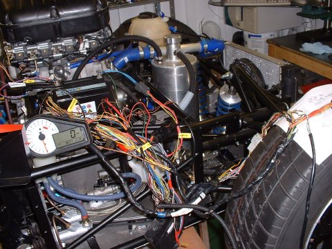
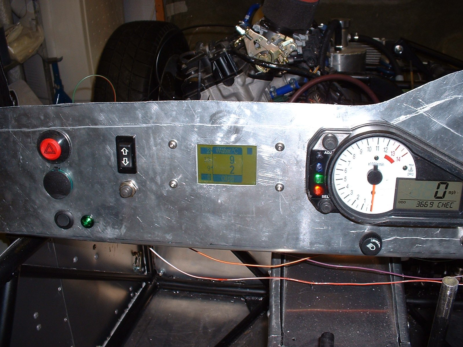
The next time I applied power - Bingo! The rev counter did it's thing, and the 'FI' error light came on. Shorting across the 'Dealer Mode' switch revealed the actual 'FI' error codes - and these indicated that the Inlet Air Pressure sensor, the Inlet Air Temperature sensor, and the Tip Over switch were all malfunctioning. The IAPS I haven't got (missing off the airbox), the IATS I'd forgotten to connect, but the TOS had me fooled for a bit; I'd shorted across where it should be in the loom. Leaving it open didn't change the error. In the end I realised that I needed some sort of resistor in the circuit to drop the voltage seen by the ECU to somewhere inbetween open and closed circuit - a 6.8k one did the trick.
The picture shows me doing 0mph, and the _C13 IAPS error code.
A day of doom and joy
- November 20 -
Doom doom doom. I went to Hallens first thing to order an IAP sensor and a Starter relay (the latter not strictly necessary, but it would be easier to plug in the original relay than to wire in a new one). They quoted £40 for the relay and £250 for the IAP sensor. Despite some mental preparation for the shock of Suzuki parts prices, I wasn't ready for that...
The girl on the Parts Counter actually seemed as shocked as I was. She muttered something that may have been 'Sorry', but I was already leaving.
But then, some luck. A parts request on bike-breakers.info had me a IAP sensor and relay for the combined price of £35, which was much more tolerable...
My advice to you - make sure the airbox you buy has one on it. You may not be so lucky...
I spent the rest of the day fiddling with more loom stuff, but the end result was the same as when I'd started!
Fiddle faddling about
- November 26 -
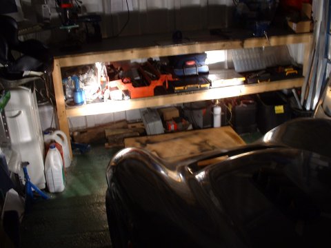
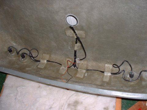
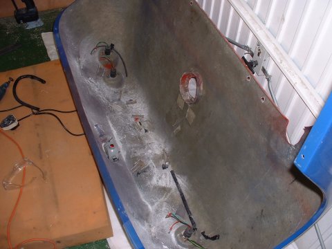
I spent most of today sorting out some of the easier electrical stuff. First job was to find a home for the battery - the lower the better to keep the CofG as low as possible. The best place turned out to be in the area in front of the brake and clutch master cylinders:
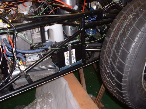
So that was the easy part. It took 2 hours the make the battery tray and the restraining strap...
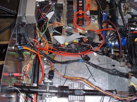
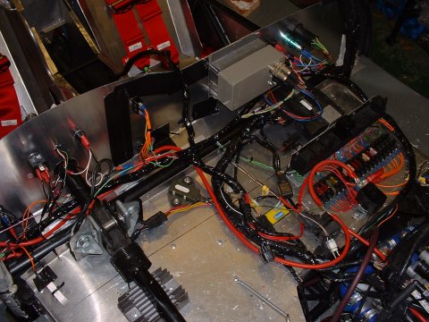
Then I rigged up a dummy under-scuttle panel to spread the loom out on, and worked out roughly where I want everything to go - which is to keep everything away from the exhaust side of the car, and to try and get the regulator into a place where I can get some airflow over it (other BEC's have had occasional problems with their regulators over-heating)
That done, I wired up the CKPS and the starter motor, as they'll be difficult to access once the coolant pipes are all in place and filled with coolant.
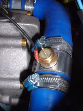
Then I went round checking that the various senders were properly earthed. The only difficult one was the coolant temperature sensor, which is in an aluminium hose joiner, which joins silicone hoses. I made up an aluminium washer with a tab on it for a spade connector, but it leaked when I trying putting coolant in the system. That left me little choice but to try and attach an earth wire to the sender itself. Soldering failed, so I tapped an M3 bolt into the side of it, which is perfectly not illustrated by the picture I took to commerate the achievement
The final dabble in electrics was to make sure that the coolant pump pumps. I can verify that it makes a whirring sound, and the coolant glugged a bit.
Getting the engine going
- November 27 -
The only thing today standing between me and a running engine, all other things being well, is: to connect the fuel pump properly, to wire up a temporary connection to the radiator fan, and to get some petrol.
The first 2 were easily achieved, and for the latter I cycled off to the local petrol station with a small fuel can that DH2 had lent me. There's something decidely strange about cycling onto the forecourt of a petrol station, and stranger still is filling up a small container with petrol and putting it in your rucksack. I cycled home very carefully - I felt like I had a bomb in my rucksack.
So, petrol in, I turned the ignition on, and gratifyingly the fuel hose bucked a bit as it filled with petrol. I checked all round for fuel leaks, double checked that everything else was as it should be, set the coolant pump going and cranked the engine over. After a couple of huffs and puffs and wheezes she fired! Everything went as it should - good oil pressure, slow and steady climb in temperature that the fan controlled perfectly. There were no fuel leaks, coolant leaks, oil leaks or air locks and all 4 exhaust headers were hot.
Yay!
Tidying the engine loom
- November 28 -
The latter part of today was spent bundling and wrapping the exposed wires in the engine loom - apart from anything else this makes it much easier to handle.
Batten down the hatches
- December 11 -
The final major job before a quick spin round the block is to get the electrics all fixed down and out of the way of any rotating bits! For some reason this took ages! All went OK, except that the CB Tech dash started misbehaving itself - despite early success, it's fan control line went haywire, so that the (radiator) fan is permanently on, and it started to do some other weird stuff too. I must have given it a voltage spike or something - I'll get Mark to fix it!
Wiring in the Yellow Box
- December 29 -
This was a nice simple job - the instructions with the Yellow box are crystal clear.
Tidying up
- February 27 -
My notes on what I did today are a little vague - "5 hours on loom". Goodness knows what I was doing. Still, another note reminds me that I did find the elusive anti-theft bypass resistor, and it is, as suggested in many other places, 100ohms.
This seems as good a time as any to mention that the 'mysterious resistor pack' mentioned elsewhere is no longer so mysterious. Suzuki have confirmed the date of manufacture of the engine as 2001, not 2002 as Ian had been told. Looking at the wiring diagram reveals that the 2001 bike has a fuel level sender resistor pack. I imagine that it can just be left out completely if the built in fuel level sender is not being used. It also answers the small (previously unasserted) mystery about why the fuel pump has 4 wires instead of 3.
Ah - now I remember. I was starting work on the feeds to the fuse box and relays. I acquired from SteveW, quite some time ago, a couple of 70A relays. I pressed one of these into service to act as the switched feed for the chassis loom, as there is no chance of any part of the bike loom coping with the demands that I will be throwing at it (including driving lights, spotlights, foglights, heated driving suit  etc
etc
The actual switched feed from the bike loom I used to feed the headlight switch. The unswitched feed I make no explicit use of, although it does provide power to the ECU, clocks and the no longer mysterious resistor pack.
By the end of the day, I'd basically got the ignition circuit working, having taken off the original bike switchgear, and run wires to my own.
Making the dash
- March 3 -
According to my notes, it took the entirety of the rest of the day to wire up all the switches with the same wires that they'd been using before I'd mounted the switches into the dash. That can't be right, but there we have it. That's what the notes say.
Relays
- March 4 -
Most of today was spent wiring up the relays both the input and output sides. I spent a goodly amount of time using little cable ties to try and bring some semblence of order to the loom.
More wiring
- March 5 -
Again, not much idea what I did today except that it was something to do with wiring.
Fitting the lights
- March 9 -
With the rear bodywork attached, now is an opportune time to start fitting the lights. Nothing too difficult here, except when I got to the headlights. I'd bought some 7" Golf Mk2 units, but when I came to figure out a way to fit them, it turned out to be impossible. There's just enough room to fit the lamp unit itself, but there's nowhere left afterwards to bolt the backplate to - the backplate being the part that actually stops the lights falling out and allows the beam angle to be adjusted...
After much despondancy and gloom, I decided to order some alternative 7" units from Vehicle Wiring Products, and get on with something else.
Which turned out to be more loom tidying and binding.
More loom work
- March 10 -
Dull dull dull. Did the front and rear loom connectors today - these will allow me to split the loom if I need to remove the bonnet and/or rear tub. During this activity I realised that I'd forgotten to run the sidelight cables out to the front of the car, which wouldn't normally consitute much of anything; but yesterday I'd spent a good long while tidily wrapping the bit of the loom that these cable should have been in. This caused me to have a bit of a strop.
MORE loom work
- March 12 -
I had NO idea I'd have to spend so much time doing wiring work. Today, I made all the earths (which to date had been temporary 'wrap-it-round-the-earthing-post') permanent. DH2 brought me round some resistors to solder onto the tails of my LED warning cluster, so I soldered them in. And I soldered in the big resistor that you get with the battery isolator switch.
Then, in a hugely successful mood boosting move, I put some more petrol in the tank, and fired the engine up again. Ostensibly this was to check that the CB tech dash was all functioning correctly, but it also enabled me to enjoy the rumbly rumbleness of the GSXR1000 engine. I was also able to verify that the fan switching works OK, and that the fan override system works properly.
Braaahmmmmmmm brahhhhmmmmmmm!
MORE headlight DOOM
- March 13 -
I tried this morning to fit the new 7" units I'd ordered from Vehicle Wiring Products. And once again I found that they DON'T FIT. Grrrrrr. They nearly fit - so nearly do they fit that I wasted 90 minutes figuring out that they DON'T FIT.
I posted on the Syvla list to see what people normally fit to Phoenix's, and the answer that came back was '5 3/4" units'. No wonder there's no room for 7" ones. Sigh.
At last : headlight un-doom
- March 15 -
Today some 5 3/4" headlights arrived from Vehicle Wiring Products. And they fit! Woo! Yay! Put all the toys back in the pram. It took about 2h to fit them, but 1h30 of this of course was the first one. Practice makes perfect and all that.
And on another upbeat note, Vehicle Wiring Products are happy to refund the money for the 7" units - they're really very nice people.
One point of note is that I've fitted the headlights dead centre of the space they sit in. This means that I can't fit the nice light covers that you can get for Phoenix's, as the top edge of the light interferes with the cover. If you're fitting covers, then mount the lights as low as you can.
All lights are go!
- March 20 -
DH2 was feeling a bit bored this afternoon, and came round to offer a hand. I indulged his passion for wiring by getting him to finish off the headlight wiring - thanks Dave!
If I'm not mistaken, that's the last of the wiring for the electric items done. Yay!
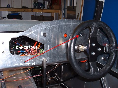
Whilst he did that, I had an unenthusiastic attempt to solve my bike clocks 'dangerous roughness' issue by removing them and trying to think of ways to mount them in a 'non-dangerous' manner. I moved the dangerously rough headlight switch to a less dangerous location as well.
More loom binding
- March 24 -
Whilst the dash is off, it's a good time to bind up all the wires that run along the back of the dashboard. As usual, this takes far longer than I thought, but it is a very theraeutic activity...
More loom binding and earths
- March 25 -
Finished! - including the section inside the bonnet and the rear tub
Also, remembered to attach the earth for the brake reservoir warning light to earth. Seems to work, as the light is on continuously, which correctly indicates that the brake reservoir is empty of fluid. Must remember to put some more fluid in it sometime. Also put a nut on the front earths, which Mr DH2 had left kinda dangling. Which he did tell me about. Which I did forget no later than 30s after he told me.
I give myself the horn
- March 25 -
In a bit of a panic, I realised that having bound the loom, I've never actually checked that I've wired up the connection to the horn correctly. I attach a bulb across the wires, and press the button with baited breath. It reassuringly honks in the only way that a light can. Phew.
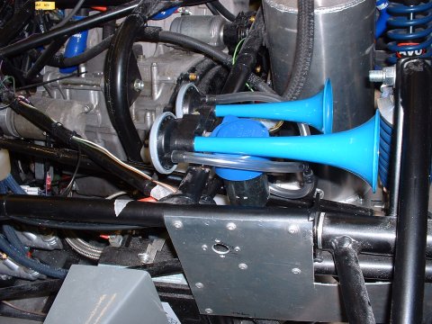
About an hour later, I've made up and welded on yet another 'turret' - this one to mount the horn compressor and trumpets on, and tested the hole schbang - a satisfyingly loud twin 'BLAAAAAAAAHHHHHHHH' this time, and nothing falls off.
(Note to self - must remember to paint the turret sometime)
Here's a picture that fails completely to show the turret, so you'll have to take my word for it that it's quite a complicated shape.
New repeaters
- April 5 -
A few weeks ago, a friend on Cam7, Carl (Hi, Carl!) sent me some old Ford style repeaters that he had taken off his TVR. I fitted these, but wasn't very hapy with them - the clips that they use to locate weren't deep enough to securely locate on the GFRP bodywork, and I'd had to silicone them on. It didn't look very good.
But recently, some Fiat Bravo ones came up on eBay, so I bought them on the chance that they'd fit better - and they did! An almost perfect fit, in fact. The only downside is that they have a sharp edge that may attract the wrong sort of attention from the SVA man. I think I can seat a bit of rubber beading on it though, so it shouldn't be a problem.
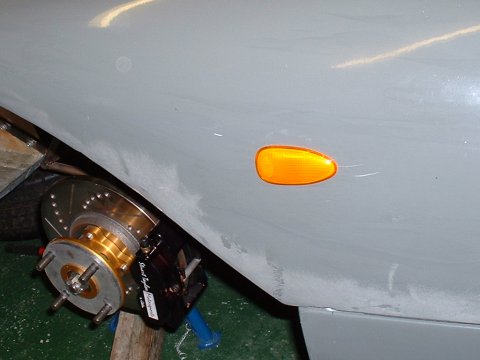
Whilst I was in a light sort of mood, I fitted on all the other light covers.
brake microswitch
- April 7 -
Wired up the brake microswitch - quite time consuming to do. A side effect of using the microswitch is that the fuel sender, which gets its power feed from the power feed to the (now bypassed) brake pressure switch now only gets power when the brakes are on - better fix that some day
Investigating fuel lights
- April 17 -
The connector for the Suzuki fuel level sender has unclipped itself - so that was a pretty easy fix.
The proper sender, however, is a bit of a mystery. The sender itself seems to be OK - with the tank somewhere around half full, the impedance of the output is 70ohms - about what I'd expect. There's continuity all the way to the input into the CBTech dash - so my assumption is that the dash itself needs some attention.
Convolutions and ECU death
- April 24 -
Today, I have mostly been corrugating my car.
Yes, today was the day for me to address the concerns of the SVA man in the area of protection of my loom against chafing. So, I Dremelled off the glass fibre I'd used to hold various sections of loom in place (and discovered that the little spiral cutting tool attachment is great for routing through GFRP where access for a cutting disc is limited). Then I wrapped every bundle of wire I could see in convoluted loom tubing. This would have been easier if I'd ordered the pre-slit stuff...
Whilst I was fiddling about with 'lectric, I tidied up the routing of the wires to the fuel sender, and gave it a proper power supply (instead of the one that was only one when the brakes were on...)
I also fitted grommets to the number-light and fog-light holes, put some thermal wrap on the N/S indicator (it sits directly above the exahaust
Then I glass fibred everything back in place, changing the routing of the rear loom whilst I was at it, to allay the SVA man's fear about 'unsupported wiring' (the rear loom used to dangle from the rear tub down to the main connector - nothing it could swing into, or get caught in, but he didn't like it)
Finally, I blew up the ECU

I didn't mean to. A wierd fault had appeared at the SVA, which I was trying to fix. There is a connector on the loom that switches 'Dealer mode' on or off, depending on whether it is shorted or not. Dealer Mode is useful in that it displays any engine fault codes on the clocks where the Engine Coolant Temperature would normally be, which makes tracking them down a bit easier. At the SVA I'd removed the little bit of wire that I'd been using to short the connector, as the SVA man would have judged is as unsecured wiring.
Having not put the wire back in before the drive home, 'Dealer Mode' was off, which it never had been before. Formerly, when the ECU was powered up, then it reported no faults. Now that 'Dealer Mode' was off, then the ECU was reporting a fault by illuminating the FI Warning light. If 'Dealer Mode' was subsequently engaged, the fault was listed as being C46 - the Exhaust Control Valve Actuator Sensor.
Checking the manual today, I found that the ExCVA sensor is expecting to see a certain voltage from the Exhaust Control Value Motor. Which I don't have. Despite ages fiddling with resistors and turning the ECU on and off, I couldn't get the fault to clear, which was annoying. Then, the fault code vanished - but only to be replaced by 'CHEC', which roughly translates as 'ECU hath vanishéd'
The ECU doesn't have a separate fuse, and the clocks still work, so I'm left with the conclusion that I've somehow put the wrong sort of electricity up the wrong hole, and blown it all to pieces. I hate electricities. They also do their utmost to be wrong.
I shall mostly spend Monday looking for a 2nd hand ECU.
New ECU
- April 28 -
On the upside, the ECU Ian has lent me seems to work OK. Phew.
Baffling
- May 3 -
DH2 yesterday commented that the most obvious place to check for a fault is the starter relay - for the motor to run, the relay must be engaged - perhaps it got stuck on?
And, having used nothing more than the power of mental thought, he was right - there was continuity across the relay terminals. Still - he has got a brain the size of a planet. But when I stripped everything down, and put power across the relay's coil, it had freed itself up, and gave a very satifying and heavy click as it engaged. And disengaged. And engaged. And disengaged. Weird. I can't detect any stickiness at all - no reluctance to engage or disengage.
I then test the switched circuit relay. That is fine too - a good, proper click when I give it power. I connect everything up as it should be, and start the engine (I'd charged the battery overnight). Engine springs into enthusiastic life.
twiddling
- May 28 -
Today, I fixed a couple of little things that had been bugging me. ! was that the FI fault light had come on again, and once again, it was the EXCVA sensor. After lots of fiddling with pulling wires out of the ECU, shorting things and fiddling with resistors, I found that a potential divider across the 3 terminals of the sensor plug in the loom did the trick. In theory, a 1:1 split in the input voltage should have done the trick, in that the manual says that sensor is supposed to see 0.2V to 4.8V, and the input voltage is 4.95 volts. However, a simple potential divider using 2 6k8 resistors didn't work. I took a guess that the ECU also worries about absolute resistance. The manual makes a vague reference to the EXCVA having a resistance of 3k1 ohms at 'the reference position'. So I decreased the resistance on one side of the divider by putting another 6k8 resistor on one side, and that did the trick.
The other thing I did was, having read this TL1000S website, I pulled the clutch position switch sensor wire out of the ECU, just in case that's contributing to the super richness of the engine (the theory being that when the clutch is pulled in on the bike, the ECU switches to a different map, which is presumably only accurately mapped for the no load sites. If the only action you take to bypass the clutch switch in the loom is to short it, then you'd be running this map rather than the one you actually want. There is no evidence to support this on the GSX-R 1000, but it's a possibility)
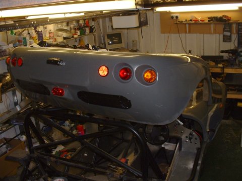
fitting the Mini foglight
- December 11 -
Yonks ago I bought a BMW Mini foglight, and this afternoon I fitted it. I used an old offcut of GFRP (the scuttle) to make up a template. It was pretty simple. The hard part was figuring out how to stop it falling out again, but a cunning arrangement of bits of bent aluminium seems to have done the trick. The picture shows the foglight and some gaffer tape mocking up some speculative holes which will let out air that channels itself up into the rear bodywork from the wheel arches - lots of race Furies and Phoenix's have something similar, and my assumption is that it aids high speed stability. Anyone got anything to say about that?
There's always something
- April 2 -
To my dismay, having spent the whole morning attaching the bodywork, the rear sidelights were not working. I was completely lost as to a reason why, as they are on separate circuits, albeit with a common earth - but everything at the back shares that earth, and everything else was OK. I checked the switch (the only common thing) - fine. Fuses were fine. Power was getting to the rear most connector (on the chassis, connects into the loom attached to the rear bodywork. I eventually tried bypassing the rear loom, taking power direct to the light from the chassis connector - and they were fine. So with a sinking heart, I resigned myself to removing the rear bodywork - the entire morning's work...
Having removed it (an hour's work) I removed the loom from it and set about testing it - and found that the problem was that both sidelight wires had been cut through by a Dremel wheel. It must have happened when I had to remove the loom after the first SVA fail, to protect it with convoluted tubing. I guess that's called irony... It also means, of course, that the sidelights were not working for either of my SVA re-tests. Strange, as I am sure I would have checked them.
A bit of splicing, soldering, heat-shrinking and convuluting (and testing!) later and the loom was ready to be glass-fibred back in.
Forwards progress again
- April 3 -
Glass-fibred in the repaired loom, and whilst I was in the area, I decide that it would be a really really good idea to take a spur off the brake light feed to the rear chassis connector, so that when I come to fit a high level brake light I won't have to remove the bodywork again. Genius, huh...
This page last updated on: Sunday, Jul 16 2006
Date
aeroscreen
body
boot
brakes
chassis
cooling
clutch
dashboard
electrics
emissions
engine
exhaust
final drive
fuel system
gear shift
lubrication
mirrors
panelling
propshaft
reverse
seats
steering
suspension
throttle
trim
wheels
garage