home
introduction
build
sva tests
links
latest updates
Gear shift mechanism
- June 15 -
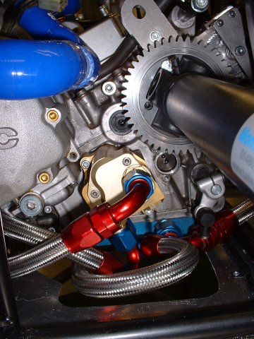
I painted the gear shift mechanism bits that Ian sent last Friday. I currently have no idea how they piece together - It's kind of like a jigsaw puzzle where you can see how all the bits might fit together, but when you try it, it doesn't seem quite right  I think I need to get the propshaft and electric reverse into the mix, so that I can see what has to go where.
In a sequence worthy of a Buster Keaton movie, I also successfully covered my hands, face and hair in POR-15...
Baffled by the gear change mechanism
- September 18 -
Next, I spent about 30 minutes trying to figure out the gear shift mechanism. And failed. I'm seeing Ian on Thursday, so hopefully he'll elucidate. In the meantime, if you're passing, and fancy a go at figuring it out, then call in
To add to the difficulties, there's not really much room left now...
Another quick visit to STM
- September 23 -
Chatting to Ian, it became clear that the kit he'd provided wasn't ever intended for my car - he'd prefer to see it with the paddle shift. Which is why there's not obvious place for it to fit
However, he's switched over to using a push-pull cable for his paddle shift cars, and gave me one to try.
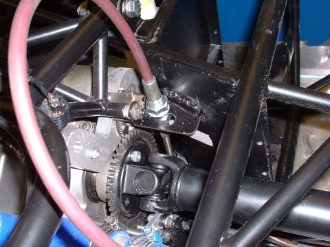
Fitting the engineside gear stop
- November 13 -
The disadvantage of using a cable for the gear shift is that it needs stops at each end. I spent a little time in October figuring a way to achieve this at the engine end and the most obvious idea was to weld a plate perpendicularly onto the outside of the pedal box. Making up a alumium template, it became clear that at the height that the plate needed to be to give the cable the right amount of travel up and down to actuate the gears, the it would be possible to attach one edge of the plate to the engine cradle as well, to give extra stiffness. Downsides were that the cable has to run within a couple of mms of the prop, and that the arm of the lever on the gear shift shaft would need to be bent through 45° to meet up with the cable.
So today, I did all of those things. You can see from the first picture that in the month in between the initial concept and the implementation, I forgot about the propshaft, and had to move the cable hole in the plate to move the cable closer to the pedal box.
Getting started on the driver end of the gear shift
- November 29 -
I spent an hour today making up some little plates to put in the tunnel to mount the gear shift lever too. Why does it take so long just cut 2 bits of metal and shape them a bit?
- November 30 -
With Alex's help to hold the them in the right orientation, I got the plates welded in. Then I made up the gear lever itself, which is an upside down offset T shape. Through the unexpected arrival of some serendipity, I'd chosen some 1/2" x 16 gauge steel tubing for this; in metric, this gives a bore of 9.5mm, which is good enough for my purposes to be tapped for an M10 bolt. So it was easier than I was expecting to bolt the T in place between the plates. I'd put some nylon washers between the plates and the tube to reduce the friction, and in my original plan was that this would be all I would need to do. But as I twiddled the lever, there was too much friction, and backing the bolts off introdcued too much slack.
Finishing off the gear shift
- December 4 -
Well, I solved the friction problem by chopping 1 cm off each end of the T. With locknuts to hold the bolts firmly in the plates, I was then able to do them up to put just enough tension into the T to stop it being slack, whilst keeping it free enough to rotate on the threads.
I'm sure that's as clear as mud - here's a picture...
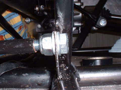
The rest of the day was spent making a(nother) bracket - this one is the stop for the cable itself. Once more, the serendipity fairy visited, and left me a convenent place to bolt the bracket to - the bracket that holds the centre bearing.
Unfortunately, luck ran out there a bit. Without having any easy way to measure the cable pull required to change gear, I chose to just guess, and mounted the cable 1/2 way between the pivot and the top of the tunnel, giving a leverage ratio of 3:1 at the point where the gear knob will be. My motivating concern was that I didn't want to have so much throw on the lever that it would hit some of the sticky out bits on the prop.
However, my guess turned out to be way too conservative - the throw on the lever was nice, being in total about 3" from front to back, but the action was very heavy, the lever was noticeably bending with the effort, and the throw at the tunnel top was only 55mm of a safe 90mm.
(For the good of future generations, the cable pull required to effect a gear change is about 13mm)
So, I unbolted the cable stop bracket, rotated it down a little so that the cable would arrive at the lever a bit lower, and drilled more holes that I didn't want to to secure it.
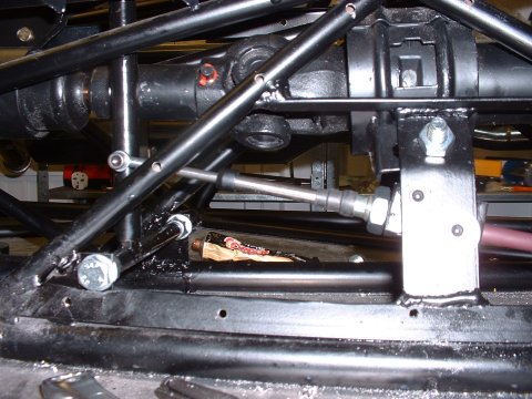
Then I decided to sleeve the bottom part of the gear shift lever, for 2 reasons. 1 - to add some stiffness, and 2 - to reinforce the 6mm hole that I'd drilled in it previously to attach the cable to.
Of course, the 5/8" x 16 gauge tubing I had to hand wouldn't quite fit over the the 1/2" tubing of the gear stick, so I had to open it up along its length with an angle grinder. During this process I discovered that red hot sparks of steel will set fire to clothing if you make enough of them and stand directly in their path.
After I'd put myself out, I bashed the sleeve over the gear shift lever and welded it in place.
A few more holes later, and Eureka! - a working gear change. The action has an acceptable weight, the lever doesn't hit the prop at either end of its travel, it doesn't seem to flex, and the throw at my hand is now about 5.5"

This page last updated on: Sunday, Jul 16 2006
Date
aeroscreen
body
boot
brakes
chassis
cooling
clutch
dashboard
electrics
emissions
engine
exhaust
final drive
fuel system
gear shift
lubrication
mirrors
panelling
propshaft
reverse
seats
steering
suspension
throttle
trim
wheels
garage